How to build a theremin
1.
materials for the theremins:
Your materials list is really quite short. You will need the following parts...
Please note that the quantity of each part is in the [ ].
-555 Timer IC [1] ( the 555 timer ic is a integrated circuit and is used in a variety is timers, as a pulse generator, and as a oscillator application.)
-100uf Electrolytic Capacitor [1] ( an electrolytic uses electrolyte ( an ionic conducting liquid) as one of its plates to achieve a larger capacitance per unit volume than other types.)
-1.0uf Disk Capacitor (Marked "104") [2]
-Photo Resistors [4]
-1K Resistor (colours: Brown, Black, Red, Gold) [1]
-a Switch [1]
-9v battery [1]
-A speaker [1]
-A IC proto board to keep it all nice and tidy [1]
-Some machine screws and nuts to hold down the board (optional)
1.
Method 1 of 4: Building the Case
-
1Find or construct a box to house the Theremin's internal circuitry. It should be large enough to make a Theremin you can comfortably play, about 24 inches (61 cm) wide for most adults.
- The top should be hinged so you can install the components and make adjustments when necessary.
Ad -
2Install the antennae.
- A monopole antenna (pitch antenna)is attached to the top of the box on the right side if you are right-handed and to the left side if you're left-handed. The pitch antenna is vertical.
- A loop antenna (volume antenna)is attached to the left side of the box if you're right-handed, and on the right side if you're left-handed. The volume antenna should be horizontal and protrude from the side of the box.


Method 2 of 4: Building the Pitch Control
-
1Create the pitch control with a variable oscillator and a reference oscillator.Each should be tuned to the same base frequency in the middle of low frequency radio range.
- Connect the variable oscillator to the pitch antenna. When playing the Theremin, your hand changes the capacitance of the antenna, which will change the frequency of the variable oscillator.
- Add potentiometers to make the relationship of your hand movement to the change in pitch more linear.
-
2Feed the output of each oscillator into a mixer. The mixer will compare the frequency of the variable oscillator with the reference frequency. The output will be an audio signal -- 20Hz to 20kHz.


Method 3 of 4: Building the Volume Control
-
1Connect a variable oscillator to the volume antenna. This should also be in the low frequency radio range and carefully tuned.
-
2Send the output of this variable oscillator into a volume resonant circuit. The output will be a DC voltage that varies according to the output of the variable oscillator. When you play the Theremin, your hand changes the capacitance of the volume oscillator, which will change the output frequency of the oscillator.
-
3Route the outputs of the mixer and the volume resonant circuit into a voltage controlled amplifier. The voltage from the volume resonant circuit changes the amplitude of the audio signal from the mixer.


Method 4 of 4: Finishing the Theremin
-
1Send the output of the voltage controlled amplifier into an audio amplifier and then a speaker. These can be internal components or a guitar amp you connect to the Theremin with a jack installed in the back of the case.
-
2Power the Theremin with 12 volts AC (alternating current). You can build a step-down transformer that will convert the normal house voltage or buy a power cord with a built in converter and your done.


How Does a Theremin Work?
Theremin works by producing sound through the interactions of two radio frequency oscillators. The frequency can be amplified if you vary the frequency and the oscillators remains fixed, the difference can be amplified this process is known as heterodyning.
2.


3.
 Remove these ads by Signing Up
-555 Timer IC [1]
-100uf Electrolytic Capacitor [1]
-1.0uf Disk Capacitor (Marked "104") [2]
-Photo Resistors [4]
-1K Resistor (colours: Brown, Black, Red, Gold) [1]
-a Switch [1]
-9v battery [1]
-A speaker [1]
-A IC proto board to keep it all nice and tidy [1]
-Some machine screws and nuts to hold down the board (optional)
4.


links:
1. http://www.wikihow.com/Make-a-Theremin
2. http://www.synthrotek.com/kit-assembly-instructions/lofi-synth-kits/optical-theremin-assembly-instructions/
3. http://www.instructables.com/id/Light-Theremin/2.
Optical Theremin Assembly Instructions
Welcome to the Optical Theremin Assembly Instructions! If you’re new to circuit-building, this is a great kit because it’s easy to build and it makes some crazy sounds. Let’s get started!
BOM Layout

Match your kit with this picture to make sure you have all the parts.
If your missing any components contact us and we’ll send you them.
Assembly
Attention: Changes may occur after the Assembly Instructions are created and the photos may not reflect those changes. Always use the BOM to verify the placement of components.
IC Socket, Capacitors, and Resistors

Solder in the IC socket. Line up the half-moon notch with the notch on the PCB.
C1 and C2 are .1uF ceramic capacitors. R2 is a 1M resistor.
Ceramic capacitors and resistors are non-polar so don’t worry about negative or positive leads.
Power Supplies

Black is negative, Red is positive

Wire up the DC jack as shown. P=Pin S=Sleeve C=Connect
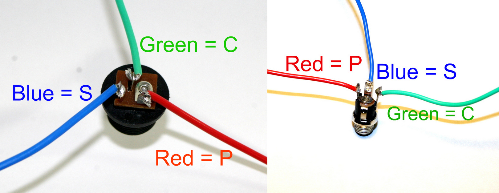
DC Jack Pinout
If you do not want to install the 9V DC jack and only install the 9V battery clip you will have to short the S and C pins for the 9V DC Jack like shown in the picture below*.
* Your PCB may not look exactly like the photo, that is ok. What is important is that you short the same pins as shown in the photo.
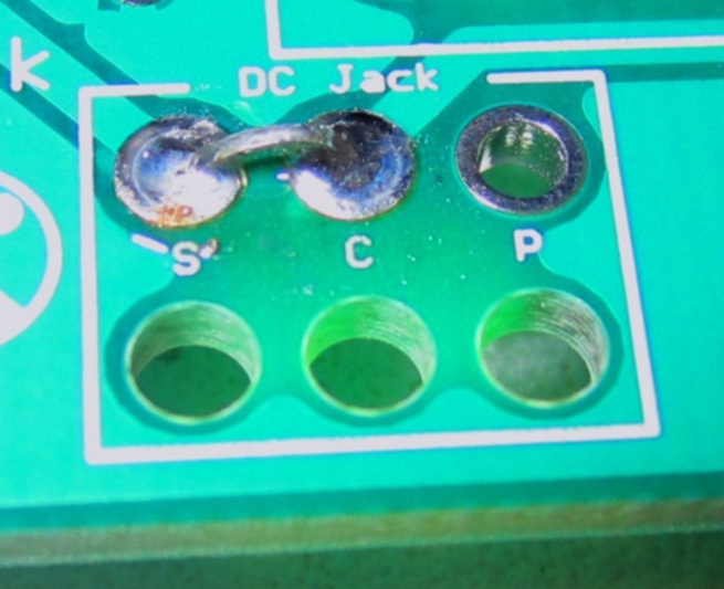
Short these contacts to get the circuit to work without the 9V DC Jack
Potentiometers


Use the pictures above.
The A100k pot will be wired on pins 1 and 2. The B1M pot will be wired on pins 2 and 3.
Don’t worry about the extra pins on the potentiometers.
Wire the pots to the PCB… R4=A100k R5=B1M
When installing the pot, some pots come with nubs near the shaft that may get in the way of installing the circuit into a case. Check for a nub and clip as necessary.

Don’t forget to cut the nubs on the potentiometers as necessary.
On/Off Switch

Wire as shown in the picture above.
Mono Jack

Wire as shown in the picture above. S=Sleeve (ground) T=Tip
Optical Resistors

R3 and R1 are the optical resistors. Wire them up in any way you choose!
Complete

Congrats!
3.

The Light Theremin is a simple to build instrument that uses light and shadows to create sound. The theremin circuit used normally for these instruments are quite complex, this one however is as simple as a 555 Timer IC and some basic components from your scrap box. so with out any more delay...Lets get started!
Remove these ads by Signing UpStep 1: Materials

Your materials list is really quite short. You will need the following parts...
Please note that the quantity of each part is in the [ ].
-100uf Electrolytic Capacitor [1]
-1.0uf Disk Capacitor (Marked "104") [2]
-Photo Resistors [4]
-1K Resistor (colours: Brown, Black, Red, Gold) [1]
-a Switch [1]
-9v battery [1]
-A speaker [1]
-A IC proto board to keep it all nice and tidy [1]
-Some machine screws and nuts to hold down the board (optional)
Step 2: The Circuit


Following the schematic provided below. solder all components to the correct pins on the timer or in the correct holes on the proto board. The switch and four photo resistors will need to be mounted out side the box through hole's; so I suggest you solder leads going to and from it. The same rule applies for the battery pack, only you will or might want to secure this with some hot glue or super glue just to keep it in place. Do not solder the photo resistors yet they will be covered in a different step!
R1: 1K Resistor
R2,R3,R4,R5: Photo Resistors
C3: 100uf Capacitor
C1,C2: 1.0uf Capacitors
Spk1: Speaker
555 Timer: 555 Timer
Sw1: Switch
R1: 1K Resistor
R2,R3,R4,R5: Photo Resistors
C3: 100uf Capacitor
C1,C2: 1.0uf Capacitors
Spk1: Speaker
555 Timer: 555 Timer
Sw1: Switch
Step 3: The Case


You will of course need a box or container to hold the circuit. I went to Dollarama and picked up a small box from the craft asile. The boxes them selves are made of pine and thus can be painted or cut very easily. Be sure to find a box that will house you're circuit, but still offer lots of space. I gave my box a coat of "coffee" colored stain to make it look old; the color alone is totality up to you. After the paint or stain has dried drill four holes for the photo resistors, one for the switch, and a 1/4" hole on the side with the speaker. For the switch and photo resistors the hole size will vary by the size of your components. Ta-Da! You're box is complete! now all thats left to do is to stuff it with the circuit.
Step 4: The Photo Resistor Array


The design is totally up to you. I just put all four in four separate corners. To do so you will have to use a drill bit that comes close to the size of your photo resistors. Then with the holes cut, place them in, and super glue them. Now solder the photo resistors as shown in the picture below. Now attach three wires, one to the left, one on the center two (the two photo resistor leads do get soldered together), and one to the right. Then lastly solder the other end of the wires to the correct pins as shown on the schematic.
Step 5: "Stuffing" The Box


Simply take your completed circuit and all other components attached and drop it in. Then armed with super glue, secure any loose items. Where you drilled the 1/4" hole on the side earlier, center the speaker over it and super glue it in place. Then Mount the completed circuit board in a spot where it can sit comfortably and allow the box to open and close fully. Once you found that spot use some hot glue or screws to secure it, repeat this for the battery pack as well. Close the box and flip the switch...
Step 6: Using The L.T.

As you can see the sound the circuit makes will change when you wave your hand over the photo resistors or change the lighting in the room. Try different motions to produce different sounds, I observed that if you shake one hand really fast over one or two of the photo resistors the L.T. will give to a erie shaky sound. Or if you more your hand like a wave over one or all four photo resistors you'll get a wavy sound (no kidding!). Most of the sounds it produces sound like they are from a cheesy horror flick from the 60's or 70's! The total amount of sounds you can produce is only limited by your hands and lighting! Now sit down (well standing might be better) and enjoy!
You can see a HD video of the L.T. at this link:
http://www.flickr.com/photos/14462918@N03/3502046867/
You can see a HD video of the L.T. at this link:
http://www.flickr.com/photos/14462918@N03/3502046867/
Build a Pocket Theremin on the Cheap

Theremin Powered
Dave Prochnow
Even if you're not familiar with the Theremin itself, it's very likely you've heard its loopy electronic tones before. Remember those spooky sound tracks from 1950s science fiction movies? Well, chances are pretty good that those oscillating noises were generated by a Theremin.
Designed by Russian physicist Leon Theremin circa 1919, the two-handed instrument was one of the first ever electronic musical instruments and the first instrument one could play without physically touching it. Thirty years after its invention, the Theremin was popularized by American synthesizer godfather Robert Moog in the 1950s and immortalized in the classic Sci-Fi flick The Day the Earth Stood Still.
A full-fledged Theremin will set you back nearly $400, but with the instructions below, you can build a pocket-sized Theremin-like instrument that won't break the bank. Unlike the real McCoy which relies on grounded variable capacitance for changing frequency and volume with the wave of a hand, our Pocket Theremin uses variations in light for producing its unearthly vibrato.
Time: 3 Hours
Cost: $18.39
Difficulty: Easy
Cost: $18.39
Difficulty: Easy
Parts
- (2) 555 timer IC (All Electronics #; $1.50)
- (2) CdS photocells (The Electronic Goldmine #G14025; $3.00)
- (2) .01 mF capacitors (All Electronics #; $0.60)
- (1) 1K resistor (All Electronics #; $0.50)
- (1) 5K potentiometer (All Electronics #VTP-5K; $1.00)
- (1) 2-Position PCB terminal (All Electronics #TER-202; $0.45)
- (1) 8-Ohm 1" speaker (All Electronics #SK-100; $1.15)
- (1) 9-Volt battery snap (All Electronics #BST-3; $1.00)
- (1) Split-Level shielded box (All Electronics #MB-100; $1.20)
- (1) Hookup wire (RadioShack #278-1224; $5.99)
- (1) 9V battery (available locally; $2)
Note: Unlike a conventional Theremin which operates on two radio frequency oscillators, this Pocket Theremin consists of an oscillator and frequency divider that are manipulated by changes in light. Be forewarned, the Pocket Theremin is very light sensitive and must be "played" in subdued lighting for achieving the best sound effects.
Steps
1. Build the circuit. Use the Pocket Theremin circuit schematic (see below) for building the complete dual 555 Timer IC oscillator and frequency divider circuit. Pick a pair of CdS photocells from the Electronic Goldmine photocell assortment. Try various photocells for different sound effects. Keep all wiring long enough to comfortably string all of the components together inside your box.
2. Wire the terminal. Use the 2-position PCB terminal as a connector for the positive (+; red) lead and ground (-; black) lead of the 9-volt battery snap. Route all the circuit's +9V connections to one pin of the 2-position PCB terminal and solder them together. Next, route all of the circuit's GND connections to the other pin and solder all wires to this pin.
3. Deconstruct the box. Disassemble the metal split-level shielded box. Remove all plugs, spring-loaded doors, and modular shields that you don't want in your final design.
4. Protect your insides. Insulate the insides of the metal box with tape, plastic tubing, or vinyl strips for preventing any of the electronic components from shorting out while playing your Pocket Theremin.

Theremin Construction
Putting the pieces together
Dave Prochnow
5. Installation. Install the complete circuit inside the box. Mount the two CdS photocells externally on opposing sides of the box. This placement will help you control the final sound effects with greater independence and dexterity. Now fix the speaker to the front of the box. Screw the red lead from the battery snap into the +9V terminal from Step 2. Screw the snap's black lead into the other terminal and route the 9V battery snap outside the box.
6. Power up. Connect the 9V battery to the battery snap. The Pocket Theremin should immediately begin to make some noise. You can control the volume of the speaker by adjusting the 5K potentiometer.
If you don't hear anything, check for short circuits between the components, wiring, and metal box. If the circuit construction looks OK, try moving your Pocket Theremin into a darker location. In a slightly darkened room, your Pocket Theremin should be capable of producing a wild, wide variety of sounds. Just move your hands over the two CdS photocells for varying the frequency and pitch of your Pocket Theremin's output.
Now go film your own retro SciFi flick, you've already got the sound effects in your pocket.
Click here for an MP3 of the Pocket Theremin in action

Theremin Schematic
Dave Prochnow
5.
Step 1: Gather Materials!


This needs very few parts, I made mine for under $20.
Here is what you need:
Two phototransistors
One TLC555 timer IC
One .047 uF capacitor
One 100 uF capacitor
One 1 megohm resistor
One 10k ohm resistor
A battery pack that holds 4 AA batteries
Some wire
A breadboard
A small speaker
Tools:
A wire stripper
Here is what you need:
Two phototransistors
One TLC555 timer IC
One .047 uF capacitor
One 100 uF capacitor
One 1 megohm resistor
One 10k ohm resistor
A battery pack that holds 4 AA batteries
Some wire
A breadboard
A small speaker
Tools:
A wire stripper
Step 2: Putting it together

This is a really easy circuit to build. Just make sure that you follow the directions. If any problems come up, I'll gladly try and help you out. Just send me a message.
And yes, the image came from here. It's a fascinating website.
And yes, the image came from here. It's a fascinating website.

1. http://www.wikihow.com/Make-a-Theremin
2. http://www.synthrotek.com/kit-assembly-instructions/lofi-synth-kits/optical-theremin-assembly-instructions/
4. http://www.popsci.com/diy/article/2008-04/build-pocket-theremin-cheap
5.http://www.instructables.com/id/How-To-Build-An-Optical-Theremin/
images on the material for the theremin:
file:///home/194382/Desktop/IMG_2875.jpg
http://rcatheremin.com/images/missingparts.png
video no how to build a theremin:
http://cnettv.cnet.com/systm-make-electricity-sing-build-theremin/9742-1_53-50003985.html
http://cnettv.cnet.com/systm-make-electricity-sing-build-theremin/9742-1_53-50003985.html
No comments:
Post a Comment